Products
| Ф680×850 Two-roller Reversible Cold Rolling Mill Group |
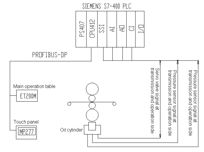
Ⅰ Rolling Condition Ⅱ Equipment Configuration: 2) Press-down AGC oil cylinder technical parameters 3) Main configuration of hydraulic system (system configuration consists three major parts): 1. Servo Hydraulic Station 2.Servo Valve Station 3.AGC Press-down Oil Cylinder (select in-built MTS position sensor) 4) AGC Servo Electric Control System Plan System network and hardware configuration are as below:
System configuration description: SIMEMZE full digital system with communication control. Compared with analog control system, the digital control system features high accuracy, without shift and non-linear problem, and the system static and dynamic state all have improved. System HMI has human-machine interaction, communication, display and saving functions, which is mainly used in data, graphical display, unit state monitoring, unit data input, information saving and other operational function screen. Site bus adopts PROFIBUS_DP that saves the mounting cost of cable installation for easier maintenance. Displacement sensor description: according to the site situation, we recommend to use the built-in digital US MTS displacement sensor in accuracy of 1um installed inside the cylinder. This sensor is encoded as absolute value and is transmitted in SSI communication signal. Under the condition of power failure, the original setting value can be memorized, which is no need of back pressure again after power on. AGC (thickness auto-control) The system adopts advanced electro-hydraulic servo control technology, and its energy provided by hydraulic pressure on the cylinder. According to the pressure feed-back signal and location feed-back signal’s servo control along with assistant tensioning, speed control, roll tilting, positive and negative bending roller control and other control methods, effectively achieving thickness the accuracy and plate-cut accuracy of rolling strip. 2.1.1 Working Principle of Hydraulic Press-on Control System APC and AFC Two closed loops’ controlling diagram is as blow
APC Working Diagram
AFC Working Diagram 2.1.2 Smooth Switching of APC and AFC The APC and AFC are two independent inner loops, and the operator can switch the position loop and pressure loop conveniently under system normal rolling process according to technical requirement without affecting the quality of the strip. Even if the operator chooses the pressure closed-loop control, when the roller hasn’t received the rolling power, the inner loop is still worked in position loop, the roller approaches rapidly, which establishes a certain rolling force and automatically enters pressure loop process without interference. When the operator chooses the position closed-loop control, roller is still at “zero” roller gap, the system will automatically switching to pressure loop smoothly, which protecting the system. 2.1.3 Roller Forced-contract Calibration As roller gap is determined by the relative position of work roller, it’s necessary to determine the zero value of the roller gap after each roller replacing, that is the pre-force-contract required by the roller. Pre-force-contract has manual and automatic modes. Manual force-contract is the manual operation of press-on rocker by the operator, driving roller contact to reach a pre-pressure. Press down “force-contract calibration” button, the roller lifts up quickly. Automatic force-contract process is the press-down “force-contract calibration” handled by the operator. The subsequent pre-force-contract processes work automatically. Meanwhile, the press-on device and transmission device related equipment are all in automatic control state with mutual interlocking. After pre-force-contract started, hydraulically press-on system automatically drives roller contact to reach preset pressure. Then, the transmission system works to make roller rotate slowly, and continuously make roller reaches preset pre-force-contract force. Set the roller position as zero, the pre-force-contract stops. Then lift up the roller, the system stops working. 2.1.4 Synchronous and Tilting Control of Transmission and Operational Side Roller Gap As there is no mechanical connection between the hydraulic cylinders at rolling mill transmission and operational side, and neither sides’ loads nor dynamic characteristics are the same, the two sides can’t keep synchronous movement. The synchronous control purpose is to accelerate the speed of slow moving side, while the fast displacement side slows down to make both sides in same running speed. In the system, the closed loop control is used to control the roller gap’s signal differences. Set the tilting adjustment button on the operational table, and adjust the roller level according to the actual conditions. 2.2 AGC System 2.2.1 Pressure AGC (F-AGC) The method principle: ensure the thickness of strip by position loop accuracy, and detect the change of incoming material’s thickness by pressure sensor mounted at the rolling transmission and operational side. Adjust the position loop output and drive the cylinder to change roller’s rolling force according to certain rolling mathematical models, which achieving the purpose of thickness difference eliminating. 2.2.2 AGC Gain Self-adaption In the rolling process, as rolling pass increases, the hardness of the strip gradually increases. The press-down efficiency decreases, and the gain of the AGC needs to be increased to ensure the dynamic response speed of the AGC system. In order to adapt to the hardness change, calculate the strip hardness coefficient according to the measured rolling force and strip press-down rate, which is used to correct the gain of AGC. 2.2.3 Thickness Compensation Control for Speed Acceleration and Deceleration Section When rolling the acceleration and deceleration section, as the small tensioning force at front and end part, the speed change greatly, it will seriously result in thickness tolerance. Speed acceleration and deceleration compensation control is based on the mathematical model of rolling mill to real-time adjust roller gap or rolling pressure, as to compensate for variations of strip thickness, and reduce the thickness error of rolling material at acceleration and deceleration section. 2.2.4 Roller Eccentricity Compensation When system is in the position loop, roller eccentricity will cause the rolling force changes, resulting in strip outlet thickness changes. Therefore, the introduction of roller eccentricity compensation, and calculate the corresponding compensation amount according to mill bounce. Then, add up the value in roller gap to compensate the thickness change caused by roller eccentricity. 3. System Related Performance Index 3.1 Repeatability precision of displacement sensor: ±0.001mm 4. Convenience of System Operation 4、1 Undisturbed switching the pressure and position loop. When the process needs constant pressure that is the pressure loop rolling (such as smooth conditions, or a displacement sensor is broken and temporary rolling one pieces by pressure ring). The system is rolling at any time, press down the position/pressure selection button on operational table, the start undisturbed switching between pressure and position loop without damaging the work roller and causing strip deformation, which greatly facilitate the operation. 4.2 The system adopted displacement sensor is US MTS displacement sensors, which is the SSI absolute-value high communication sensor, with function of keeping original pressure on the force-contract value. As there’s no change of roller or mechanical position, it is no need of twice force-contract. General SONY displacement sensor will lose the original force-contract value after power failure, which requires twice force-contract. 4.3Wear roller gap setting. As for convenient wearing of operational table and rapid press on between two works, the system sets up a wear roller gap position, which is the system rapidly layouts the wear position after force-contract other than the system rapidly drops the oil cylinder to the bottom after force-contract. If it drops to the bottom, after the operator finishes wearing or troubleshooting, it requires a long time to make oil cylinder press-down to contact working roller, which reduces the working efficiency. 4.4 Quickly lifting up. After force-contract, the system has a rapid lift button. When pressing down it, the two working rollers fast approach wear position, other than the cylinder dropping to the bottom. 4.5 Temporarily lifts up the roller. Before force-contract, temporarily lifting up the roller is same as fast lifting, which also are make oil cylinder drop to the bottom. When the system is rolling, temporarily lifting up the roller is just to make working roller “temporarily” takes off mm roller gap. When rotating the knob, the system will automatically back to the position or pressure before lifting up the roller. Such as once operators find there is a flaw on the strip, can’t be pressed and only can make through of it once, and roll it again after passing it. At this moment, it can use temporary roller lifting up function. As it is difficult for the operator to find the position of rolling state, its recovery means the improved efficiency. When not in rolling working state, unscrew the "temporary roller lifting function to make oil cylinder drop to the bottom, as to ensure the safety after work. 4.6 lt synchronous operation. When strip shape is bad, rolling-plate operator need to force the "left" or "right" tilting, the system tilting makes rolling centerline as the center, which synchronously pressing down and lifting up other than unilateral lifting and unilateral descending, which won’t damage the work roller, thus protects the roller. 4.7 Establishment and use of pass schedule. The user can edit the rolling process pass schedule (each time’s press-down quantity) in a Table and save it in the PLC. The operator makes automatic press-down when using it to achieve outlet thickness purpose. (2)Rack Assembly: 1.Two plates of closed memorial archway (pistol section 420×520mm); (3)Roller device 1.Roller dia. × roller surface widthФ680×750 Material: 9Cr2Mo (4 )Main transmission: 1.Transmission method: Two roller transmission Ⅲ Hydraulic rectangular pyramid recoiling machine: two sets 1.Roll dimension: Ф508×750mm Harmomegathus quantity: 30㎜ |
| 上一页:φ350/φ1100×1400 Technical specification of four rollers reversing cold mill unit 下一页:Ф170/Ф750×850 Four-roll Hydraulic AGC Reversible Cold Mill Unit |
  |